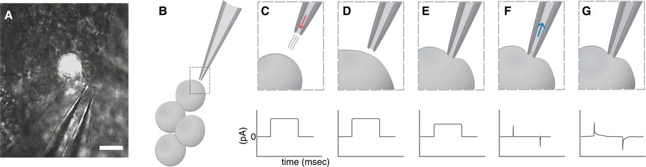
(A) Photograph of the accessory medulla area of an adult Drosophila brain magnified 60× showing exposed neuronal somas, including an lLNv marked with fluorescence. The protease pipette used for glial removal is shown nearby for comparison of scale. Scale bar, 10 µm. (B) Schematic of a patch pipette beside four large lateral ventral neurons (lLNvs). (C–G) Step-by-step schematic of patch pipette positions needed to achieve whole-cell configuration (top panels) and the corresponding signals in Clampex (bottom panels). (C) (Top) As the pipette approaches the target cell, a small amount of positive pressure needs to be applied (red arrow) to prevent debris from adhering to the tip of the pipette. (C) (Bottom) A current square step (seal test) should appear in Clampex. (D) (Top) Once the pipette is close enough, positive pressure should be stopped. (D) (Bottom) The current square step from C should show no change. (E) (Top) The pipette touches the cell, making a little depression that is visible under the microscope. (E) (Bottom) The square current step begins to flatten, as touching the cell produces an increase in resistance. (F) (Top) Negative pressure (blue arrow) is applied through the patch pipette to achieve the giga-seal. (F) (Bottom) When the giga-seal is achieved, the square current step becomes a flat line, with two very narrow capacitive transients. (G) (Top) After applying sharp negative pressure, the cell opens and whole-cell patch-clamp configuration is achieved. (G) (Bottom) Once the cell has opened into whole-cell configuration, the capacitive transients from F (bottom) widen.